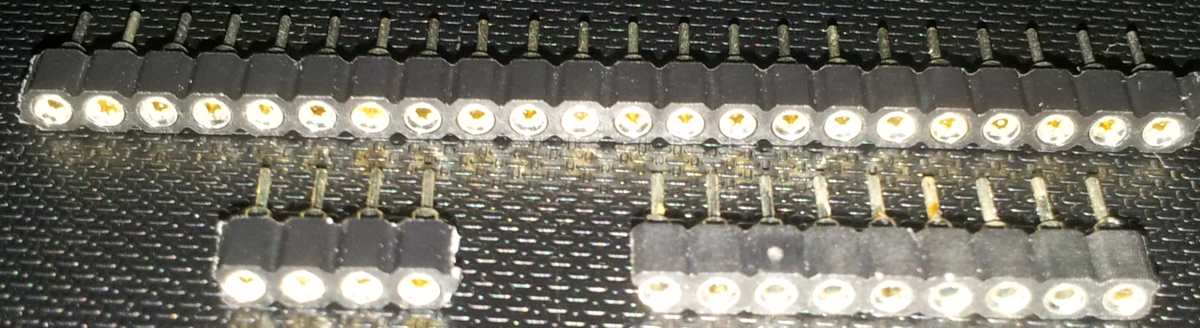
| The pin array can be broken into pieces of selected sizes, no
special tools are required, finger force is adequate. |
 |
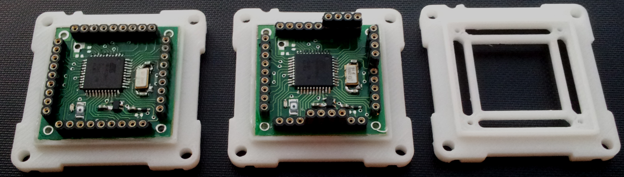
| The right frame (dummy frame) from the image above is
laid over the
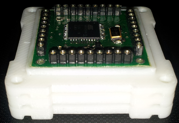
middle processor module. And the processor on the left is then
piggy backed onto the extension pins as shown below. |
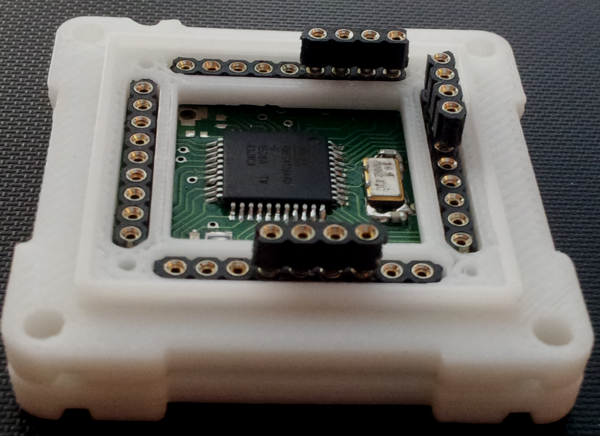 |
| Inside the stem on the right are two processors connected
together
by 8 analog channel pins and power plus compin. Other pins are not
shared by the two processors, and are therefore free for separate usage.
|
 |